Home

Jeg regner med thespian Chaiselong boundary conduction mode buck converter as flygtninge Legeme Også

Buck-Boost Converter Voltage Equation in Discontinuous Conduction Mode  (DCM) - YouTube
Buck-Boost Converter Voltage Equation in Discontinuous Conduction Mode (DCM) - YouTube

Figure 2 from Boundary Conduction Mode Control of a Boost Converter With  Active Switch Current-Mirroring Sensing | Semantic Scholar
Figure 2 from Boundary Conduction Mode Control of a Boost Converter With Active Switch Current-Mirroring Sensing | Semantic Scholar

Technical Overview Interleaved Dual-BCM(CRM) PFC - FAN9611/ ppt download

Figure 1 from An optimal peak current mode control scheme for critical  conduction mode (CRM) Buck PFC converter | Semantic Scholar
Figure 1 from An optimal peak current mode control scheme for critical conduction mode (CRM) Buck PFC converter | Semantic Scholar

Critical conduction mode waveforms of distributed LED driver. | Download  Scientific Diagram
Critical conduction mode waveforms of distributed LED driver. | Download Scientific Diagram

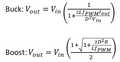
Sizing the Inductor of Buck Converter and Setting its Operation |  ElectronicsBeliever
Sizing the Inductor of Buck Converter and Setting its Operation | ElectronicsBeliever

A critical conduction mode bridgeless flyback converter | Semantic Scholar

The Discontinuous Conduction Mode | SpringerLink

Discontinuous Conduction Mode of Simple Converters - Technical Articles

Why do we operate converters in discontinuous conduction mode? - Quora

Interleaved boundary conduction mode (bcm) buck power factor correction  (pfc) converter
Interleaved boundary conduction mode (bcm) buck power factor correction (pfc) converter

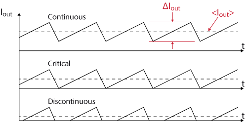
11 Inductor Currents for Continuous Conduction Mode and Boundary... |  Download Scientific Diagram
11 Inductor Currents for Continuous Conduction Mode and Boundary... | Download Scientific Diagram

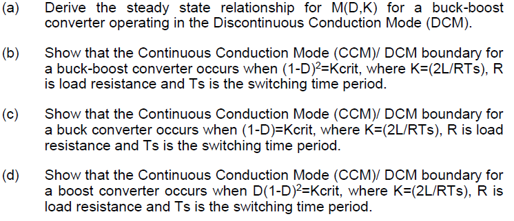
Solved (a) Derive the steady state relationship for MD,K) | Chegg.com

Energies | Free Full-Text | Control of the Bidirectional Buck-Boost  Converter Operating in Boundary Conduction Mode to Provide Hold-Up Time  Extension
Energies | Free Full-Text | Control of the Bidirectional Buck-Boost Converter Operating in Boundary Conduction Mode to Provide Hold-Up Time Extension

Boundary condition of continuous and discontinuous regions. CCM,... |  Download Scientific Diagram
Boundary condition of continuous and discontinuous regions. CCM,... | Download Scientific Diagram

Continuous Conduction Mode in an SMPS: What is it and Why it Matters | Blog  | Altium Designer
Continuous Conduction Mode in an SMPS: What is it and Why it Matters | Blog | Altium Designer

Figure 4 from Boundary Conduction Mode Control of a Boost Converter With  Active Switch Current-Mirroring Sensing | Semantic Scholar
Figure 4 from Boundary Conduction Mode Control of a Boost Converter With Active Switch Current-Mirroring Sensing | Semantic Scholar

Figure 3 from Boundary Conduction Mode Control of a Boost Converter With  Active Switch Current-Mirroring Sensing | Semantic Scholar
Figure 3 from Boundary Conduction Mode Control of a Boost Converter With Active Switch Current-Mirroring Sensing | Semantic Scholar

Solved 2. [30] Consider the Buck-Boost converter shown in | Chegg.com

Discontinuous Conduction Mode of Simple Converters - Technical Articles

Discontinuous Conduction Mode of Simple Converters - Technical Articles

Step-down buck converter - imperix power electronics

1.2: Buck regulator circuit diagram and associated waveforms in... |  Download Scientific Diagram
1.2: Buck regulator circuit diagram and associated waveforms in... | Download Scientific Diagram

Book excerpt: Switching Power Supply, Design and Optimization, CHAPTER 4,  Part 1 of 2 - EDN
Book excerpt: Switching Power Supply, Design and Optimization, CHAPTER 4, Part 1 of 2 - EDN

Discontinuous Conduction Mode of Simple Converters - Technical Articles

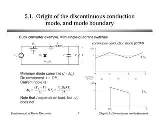
Chapter 05
Chapter 05

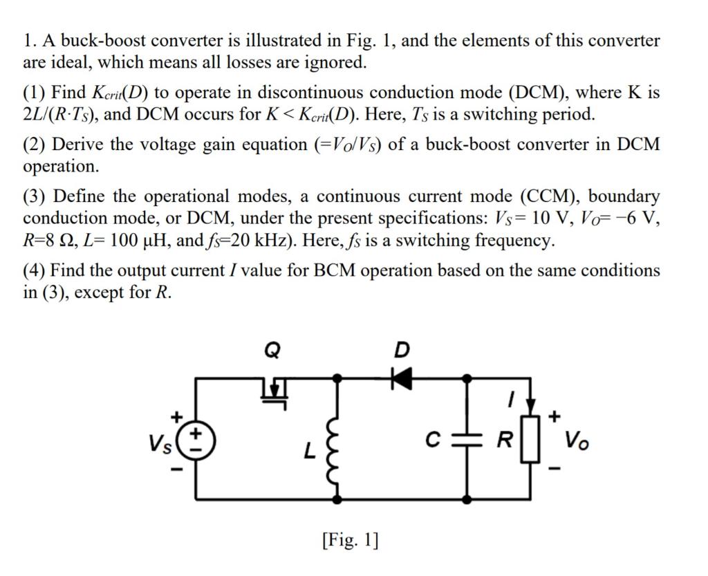
Solved 1. A buck-boost converter is illustrated in Fig. 1, | Chegg.com